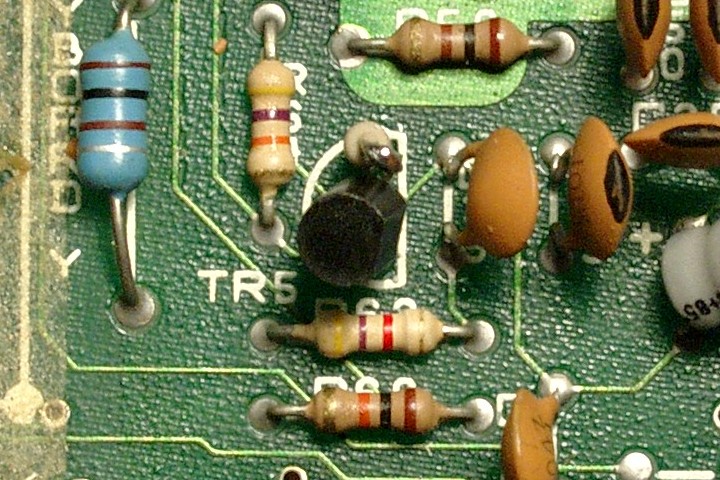
The badly distorted AY sound on an original ZX Spectrum +3 can be fixed by adding a 220 ohm resistor between the emitter of TR5 and ground as shown in the following images (the board in the images is ISSUE 2). The easiest and probably the only non-destructive way to do it is to de-solder the transistor (it helps a lot here if you have a de-soldering pump), bend its emitter leg upwards and re-solder its two remaining legs back into the PCB as they were before de-soldering. One leg of the resistor is then soldered into the empty hole in the PCB where the transistor's emitter leg used to be. Finally, the free leg of the resistor is connected to the bent transistor's emitter leg by carefully soldering them together. The fix shouldn't take more than half an hour to do (including case disassembly, reassembly and testing) and is well worth the effort (the +3 now plays the demo on page 142 of the manual in even more of its full glory).