|
|
|
|
|
|
| Welcome | ||||
| About |
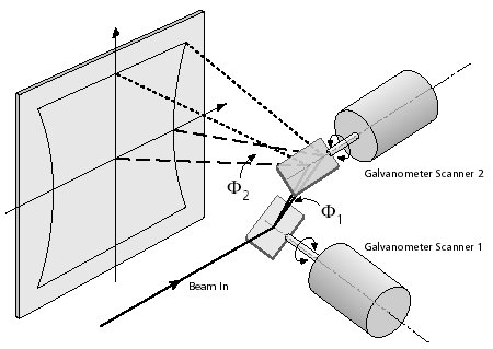
Laser scannersA scanner is a device that is able to move laser beam with two mirrors in two dimensions: first mirror moves along X axis and the second along Y axis. The mirrors are fixed on the galvanometers. A galvanometer is a motor whose rotor can turn only for cca 20 degrees. Position of the galvanometer rotor is controlled by input voltage. Due to their lightness the rotor and the mirrors can move very fast. It leads to a fast marking (burning out) with the laser beam which is a great advantage comparing to mechanic appliances for cutting object out of different materials.
The control signals for the galvanometer scanners are transfered digitally from PC interface board to the scan head. The digital interface inside the scan head converts the data to analog values, that are subsequently transmitted to analog regulator circuits that control the position of the deflection mirrors.
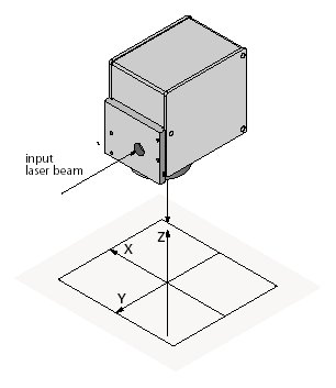
Marking of an image is based on jump and mark commands. Jump and mark commands are described with short vectors and because laser scanners are usually able to mark only straight lines, the conversion of the image into number of short lines is necessary. This is just one of the problems that occure. Although some manufacturers of the components provide solutions, all problems can now be solved on PC in real time. ZAMISEL d.o.o., specialized on PC solutions, offers a software solution for conversion of an image as FDDRO DLL (fddro-1-stran.pdf) that can read several different file formats and transform them into series of small lines which can be executed on laser scanner. The X axis, Y axis and optional Z axis of the reference system for the image field must form a right-handed system. The origin of the reference system is the center of the image field.
The size of the usable image field is determined by the maximum scan angle and the focal
length of the objective or the distance between scan head and the image field.
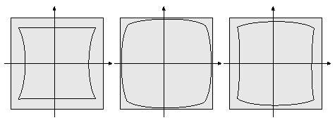
The deflection of a laser beam with a two-mirror system results in three effects:
ZAMISEL d.o.o. offers a software solution package of programs that eliminate the image field distortion effect. More information is available in the file rectification.pdf which is available on request by email. Source: SCANLAB's PC Interface Board RTC3 Manual. SCANLAB produces scan heads for the galvanometer scanners. |
|||
| Activities | ||||
| Software dev. | ||||
| Software solutions | ||||
| Triangulation | ||||
| Laser scanners | ||||
| Stepper motors | ||||
| Converting OS/2 | ||||
| Converting Win | ||||
| Circular arcs | ||||
| IDA-STEP | ||||
| Lectures | ||||

|
||||
(c) ZAMISEL d.o.o. |